Download Program At90s2313 With Arduino Lcd


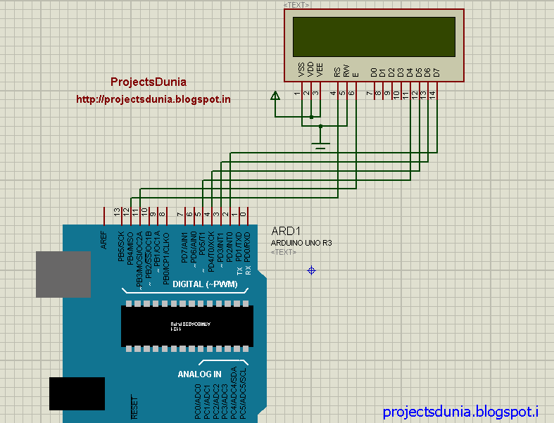
So you want to set up your LCD module with your Arduino – but jeeze! What to do with all those pins? Which ones go where?
Are there anything things to look out for when buying or setting up a new LCD Module?Glad you asked because that is what this tutorial will seek to answer.This lesson will include:. What to consider when buying an LCD module. Step by step diagrams to show what LCD pins to connect to your Arduino. Secrets of the Russian Mafia.Want to jump-start your Arduino skills?What to consider when buying an LCD module for Arduino (If you already have an LCD skip to the next section)Notice some verbiage as we talk about LCDs, you will keep seeing the two words “LCD Module”. This is because, when you buy LCD screens – you are more than likely going to buy it as a “plug-and-play” module.The LCD screen itself is a subcomponent of the module, which includes other components and circuitry that make interfacing with the LCD screen far more accessible.
The Most Important Thing to Consider:Let’s cut to the chase – the MOST important thing you need to ensure when you are buying your LCD is that is compatible with. Let me say that bigger:“Your LCD must be compatible with Hitachi HD44780 driver.”But don’t worry. This driver is so common it is pretty much the standard. If you can’t find any documentation to support whether or not the LCD you want to buy will work, then check the pin out. Does it have 16 pins?

If the answer is yes, you should feel pretty comfortable that it is compatible.So why do we need an LCD that is compatible with the Hitachi HD44780 driver? It’s because the LiquidCrystal Library that we will be using to control the LCD from the Arduino uses the driver as its standard. The functions in the library won’t necessarily work on other types of LCD screens. Some other things to consider: Size:The size of the display will be given in the number of character in a row and then the number of rows.In the picture below, the LCD would be advertised as a 16 X 2 segment.Some of the more common sizes are 16 x 2, 20 x 2 and 20 x 4, and the bigger 40 x 4. Colors and backlights:LCDs can also come in different colors – so you don’t have to go for the standard martian green. Plus, they can have backlights to help make the characters to stand out better in different light settings. Pin Out Accessibility and PCB Markings.The LCD you buy will have 16 pads where you will hook up wires or headers to connect to your Arduino, but many manufactures have made modules that also have a second set of 16 pins that are simply duplicates of the first.The one I use in this video tutorial series has a set of 16 pads at the top of the LCD and 16 pads at the bottom.
Download Program At90s2313 With Arduino Lcd Replacement
What this provides for is more flexibility in where you can connect your wires to control the LCD.For example, if you plan on mounting your LCD panel in some type of enclosure, maybe the bottom pins would be more accessible. You can also use some pads on the top and some on the bottom – since they connect to the same thing on the LCD module the top and bottom pins are interchangeable.You may also consider soldering on to the module. These make connecting your LCD to a breadboard for prototyping about a million times easier. You may not be able to find a 16 pin header, but they are made to be clipped to your desired length.The final thing I would mention is to check the pin numbering on the PCB. The LCD module I bought only had the numbers 1 and 16 on the far sides of each of the pads. This made it a little confusing when trying to figure out which wire to hook where.That just about sums everything I can think of when it comes to deciding on your LCD module – so lets go ahead and hook one up!